
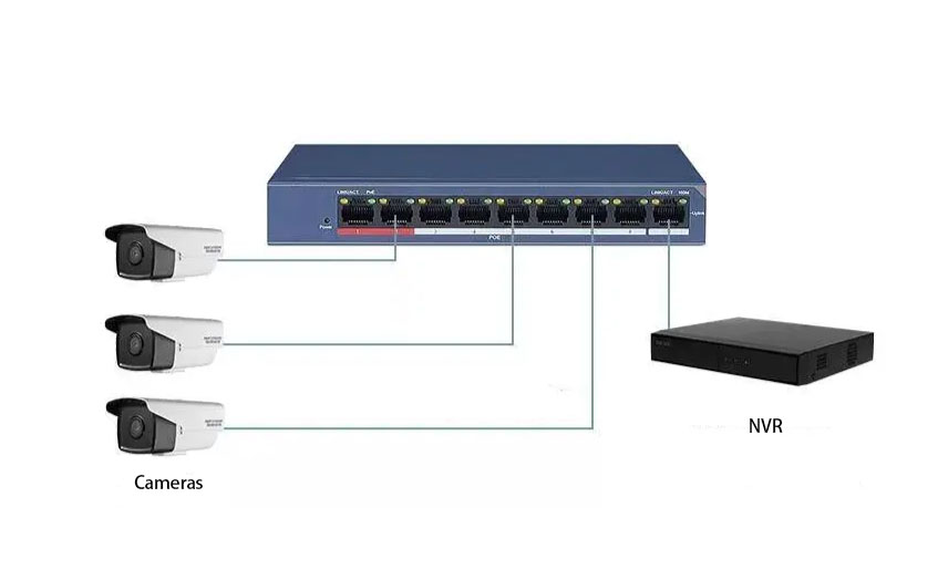
Power over Ethernet (PoE) technology allows both data transmission and power delivery through a single Ethernet cable, which greatly simplifies the installation of IP surveillance systems.
For CCTV installers and system integrators, understanding PoE standards, wiring methods, power limits and transmission distance is essential for building stable surveillance networks.
This article explains how PoE works and how to choose the right PoE switch for IP cameras.
1. Which Ethernet wires carry data and which carry power?
Standard PoE switches mainly follow two IEEE standards:
- IEEE 802.3af
- IEEE 802.3at
Both standards support two power delivery modes.
Mode A – Data Pairs Carry Power
Pins 1, 2, 3 and 6 carry both data and electrical power.
This method is commonly used by many PoE switches.
Mode B – Spare Pairs Carry Power
Pins 1, 2, 3 and 6 transmit data, while pins 4, 5, 7 and 8 provide electrical power.
This method uses the spare wire pairs in the Ethernet cable.
The good news is that PoE IP cameras are compatible with both methods.
The PoE switch and powered device automatically negotiate which mode to use.
2. Ethernet speed and cable wiring requirements
Different Ethernet speeds use different numbers of wire pairs.
Fast Ethernet (100Mbps)
Fast Ethernet uses 4 wires:
1
2
3
6
These four wires are responsible for data transmission.
In many PoE systems, these same wires can also carry power.
Gigabit Ethernet (1000Mbps)
Gigabit Ethernet uses all 8 wires in the Ethernet cable.
1 2 3 4 5 6 7 8
Therefore, when using Gigabit PoE switches, the Ethernet cable must have all eight conductors connected.
This is why 8-core network cables are required for gigabit PoE installations.
3. PoE standards and power limits
The most common PoE standards used in IP surveillance are:
| Standard | Maximum Power | Typical Device Power |
|---|---|---|
| IEEE 802.3af | 15.4W | 12.95W |
| IEEE 802.3at | 30W | 25.5W |
| IEEE 802.3bt | 60W – 90W | High power devices |
IEEE 802.3af
Maximum port output power:
15.4W
Typical usable power for devices:
12.95W
Suitable for:
- Standard IP cameras
- Basic fixed cameras
- Low power surveillance devices
IEEE 802.3at (PoE+)
Maximum port output power:
30W
Typical usable device power:
25.5W
Suitable for:
- IR cameras
- Motorized zoom cameras
- Some PTZ cameras
IEEE 802.3bt (PoE++)
Maximum power:
60W – 90W
Suitable for high power devices such as:
- PTZ cameras
- High performance surveillance cameras
- Access points
- LED lighting devices
When selecting a PoE switch, always check the power consumption of the camera to ensure the switch can provide sufficient power.
4. How far can PoE transmit power?
A common question in CCTV installations is:
Can PoE power be transmitted beyond 100 meters?
The official Ethernet standard defines the maximum transmission distance as:
100 meters (328 feet)
This includes:
90m permanent cable
+
10m patch cables
Why do some switches claim 200m or 300m PoE distance?
Some PoE switches offer Extend Mode or Long Distance Mode.
When enabled:
- Data speed may drop from 100Mbps to 10Mbps
- Power transmission distance can extend beyond 100 meters
In these cases, distances such as:
- 200m
- 250m
- 300m
may be possible depending on cable quality.
However, for most professional CCTV installations, it is still recommended to keep the distance within 100 meters.
5. Why Ethernet cable quality matters for PoE
The transmission distance and stability of PoE are strongly affected by cable resistance.
Different Ethernet cable materials include:
- Copper-clad steel
- Copper-clad aluminum
- Copper-clad copper
- Oxygen-free copper
Among these options, oxygen-free copper cables provide the lowest resistance and best conductivity, making them ideal for PoE power transmission.
Power loss in Ethernet cables
Power loss can be calculated using the formula:
Q = I²Rt
Where:
- I = current
- R = resistance
- t = time
This means:
- Higher resistance leads to higher power loss
- Longer cable distance increases resistance
- Higher resistance reduces PoE stability
Best practice for stable PoE installations
For reliable PoE performance:
- Keep cable distance within 100 meters
- Use Cat5e or higher Ethernet cables
- Prefer oxygen-free copper cables
- Avoid low-quality copper-clad cables
These steps help ensure stable power delivery and reliable IP camera operation.
Conclusion
PoE technology greatly simplifies IP camera installations by allowing power and data transmission over a single Ethernet cable.
To build a stable PoE surveillance system, installers should consider:
- PoE standards (802.3af / 802.3at / 802.3bt)
- Camera power requirements
- Ethernet cable quality
- Transmission distance
- Switch port power capacity
Choosing the right PoE switch and using high-quality cables will ensure long-term reliability for CCTV systems