
In security surveillance projects, different power supply methods should be selected according to the actual installation environment.
Currently, the main power supply methods for surveillance cameras include:
- Independent Power Supply
- Centralized Power Supply
- PoE Power Supply
Among them, PoE power supply can be implemented in four different deployment scenarios.
Below is a brief introduction to the characteristics, advantages, and disadvantages of each method.
1. Independent Power Supply Mode
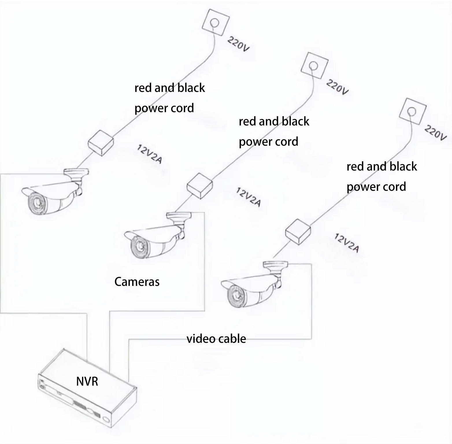
Independent power supply means installing a separate surveillance power supply unit for each camera, where each power supply provides power to only one camera.
Advantages of Independent Power Supply
Easy Maintenance and Replacement
Since each camera has its own independent power supply, troubleshooting becomes easier.
When a camera fails:
- The faulty camera can be quickly identified
- If the issue is caused by the power supply, only that single power supply needs to be repaired or replaced
Prevents System-Wide Failure
In centralized power systems, if the power supply fails and no UPS backup is installed, the entire surveillance system may stop working.
However, with independent power supply:
- A power failure will only affect one or a few cameras
- The rest of the system will continue to operate normally
This helps prevent complete system paralysis.
Disadvantages of Independent Power Supply
Higher Cost
The total cost of multiple independent power supplies is usually higher than a centralized power supply with the same output capacity.
Higher Risk of Physical Damage
Independent power supplies are usually installed close to the camera.
In outdoor environments, they are more likely to be affected by:
- Sun exposure
- Rain
- Lightning
- Other environmental factors
Therefore, when used outdoors, it is important to select outdoor-rated surveillance power supplies with proper protection levels.
2. Centralized Power Supply Mode
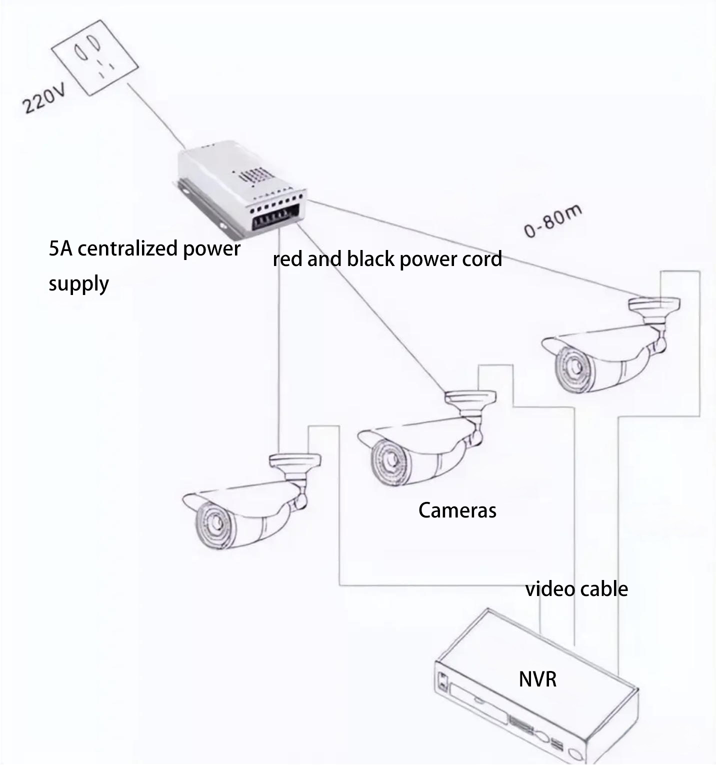
Centralized power supply means installing one 12V switching power supply at the main power source (220V) and distributing power to multiple cameras.
Typically:
- 2×1.0 red/black power cables are used to connect cameras
- The recommended 12V transmission distance should not exceed 100 meters
In this setup, a centralized power supply installed in the control room or an intermediate location supplies power to all front-end cameras.
The biggest difference compared with independent power supply is that one power supply unit can power multiple cameras.
Advantages of Centralized Power Supply
Lower Cost
Although centralized power supply often requires more cabling, centralized power units are usually more cost-effective.
As a result, centralized power systems often provide the best cost-performance ratio.
Easier Centralized Maintenance
Centralized power supply offers:
- Easier cable management
- Convenient installation
- Simplified system management
Lower Overall Energy Consumption
Based on real engineering project experience, the total energy consumption of centralized power systems is usually lower than independent power systems.
Disadvantages of Centralized Power Supply
Complex System Design
Surveillance cameras require high startup current during power-on.
Additionally, long-distance power transmission causes voltage loss.
Therefore, the total power of the centralized power supply cannot simply equal the sum of all camera power ratings.
Proper system design requires engineers to have a complete understanding of the entire surveillance system.
Risk of System-Wide Failure
If a centralized power system fails and no UPS backup power is installed, the entire surveillance system may stop working.
3. PoE Power Supply mode
PoE (Power over Ethernet) transmits both power and data through a single Ethernet cable.
There are four common PoE deployment scenarios.
Scenario 1: Both Switch and Terminal Support PoE
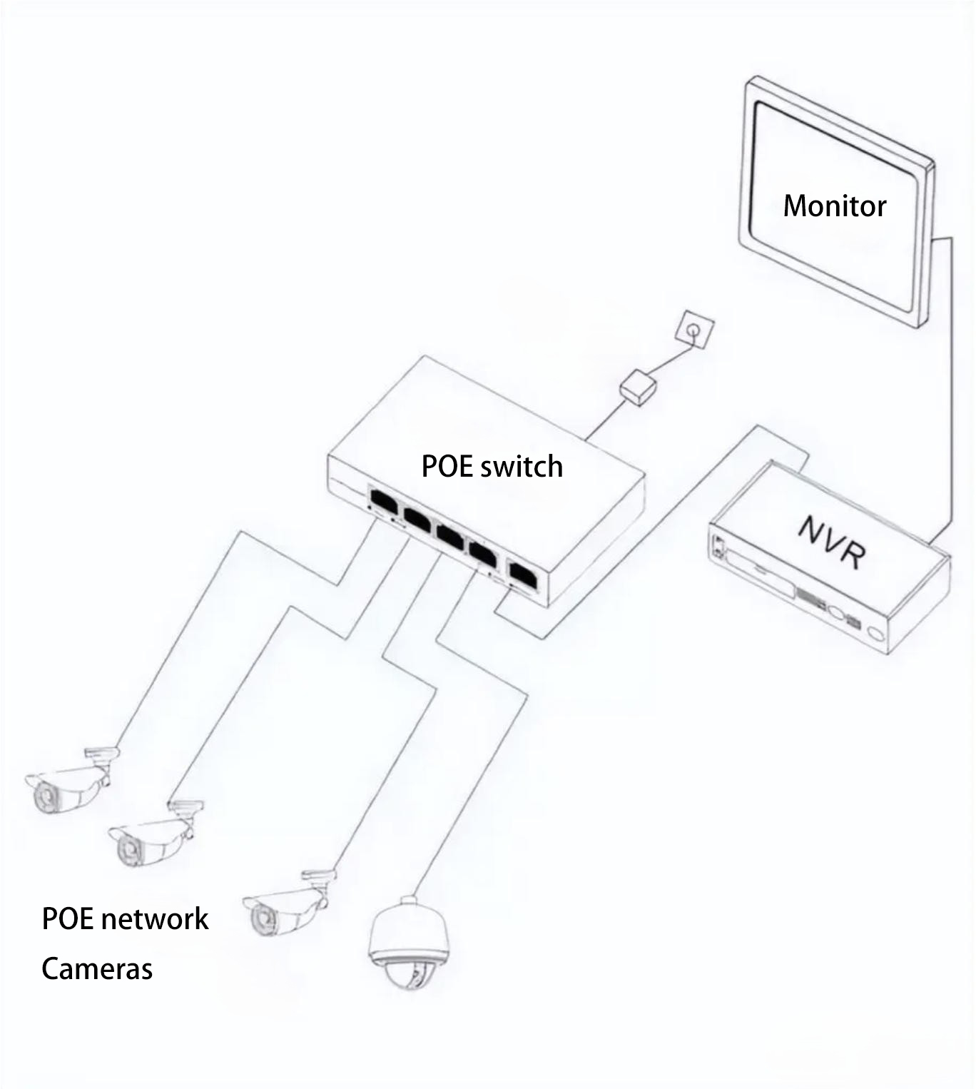
In this setup:
- A PoE switch connects directly to
- PoE-supported devices such as IP cameras or wireless APs.
This is the simplest deployment method.
However, pay attention to the following:
- Ensure both the PoE switch and the camera/AP support standard PoE
- Use high-quality Ethernet cables
Poor cable quality may cause:
- Device power failure
- Frequent camera rebooting
Scenario 2: Switch Supports PoE but Terminal Does Not
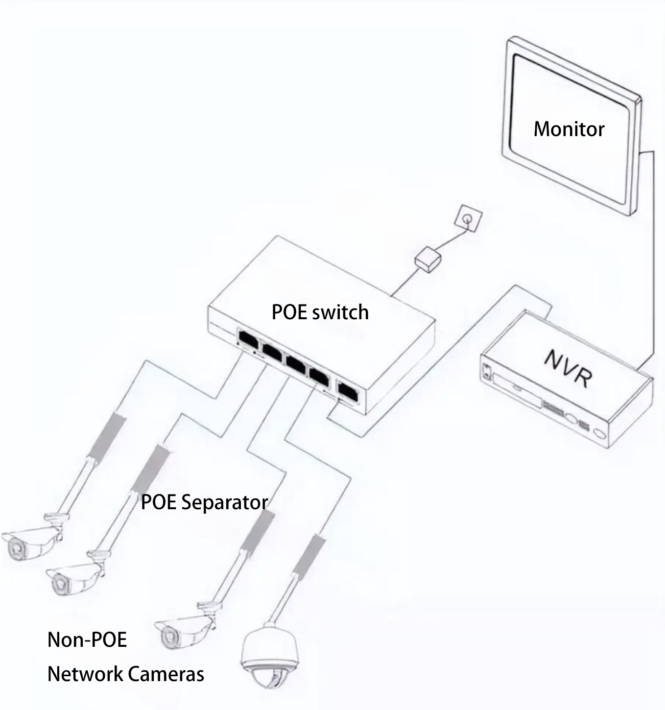
In this case:
- A PoE switch connects to a PoE splitter
The PoE splitter separates the signal into:
- Power output
- Data output
The outputs include:
- One power cable
- One Ethernet data cable
Power output options may include:
- 5V
- 9V
- 12V
This allows compatibility with non-PoE devices that use DC input power.
The splitter supports IEEE 802.3af / 802.3at standards.
Scenario 3: Switch Does Not Support PoE but Terminal Supports PoE
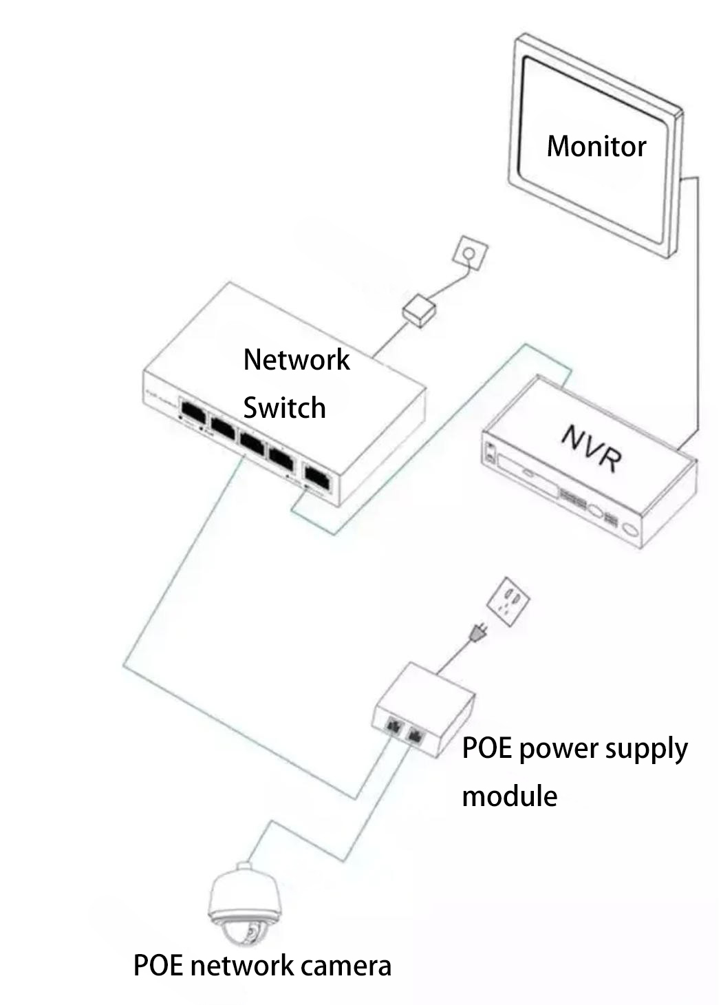
In this scenario:
- A PoE injector is installed between the switch and the terminal device.
The injector adds power to the Ethernet cable before transmitting it to the terminal device.
This solution is useful for:
- Upgrading existing network infrastructure
- Adding PoE functionality without replacing the existing switch
Scenario 4: Neither Switch nor Terminal Supports PoE
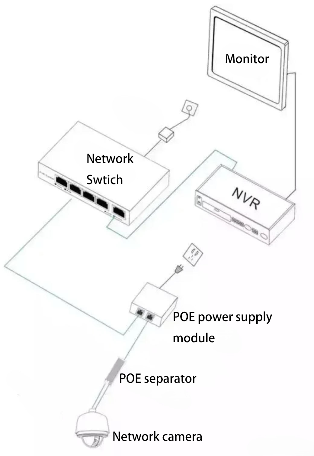
In this setup:
- Switch → PoE injector → PoE splitter → terminal device
Scenarios 3 and 4 are commonly used when upgrading traditional network systems that originally did not support PoE.
How to Choose the Right Power Supply Method
Each power supply method has its own advantages and disadvantages.
The final choice depends on:
- Installation environment
- System scale
- Client requirements
General recommendations:
| System Size | Recommended Power Method |
| Up to 4 cameras | Independent power supply |
| 4–16 cameras | Centralized power supply (if distance is similar) |
| More than 16 cameras | Multiple centralized power supplies combined |
Proper system planning and power calculation should always be done before deployment.