
How to wire the alarm function for Dahua dome cameras? How to configure the alarm settings? Follow the steps below to easily resolve this issue.
Step 1: Connect the alarm input device, as shown in the diagram below.
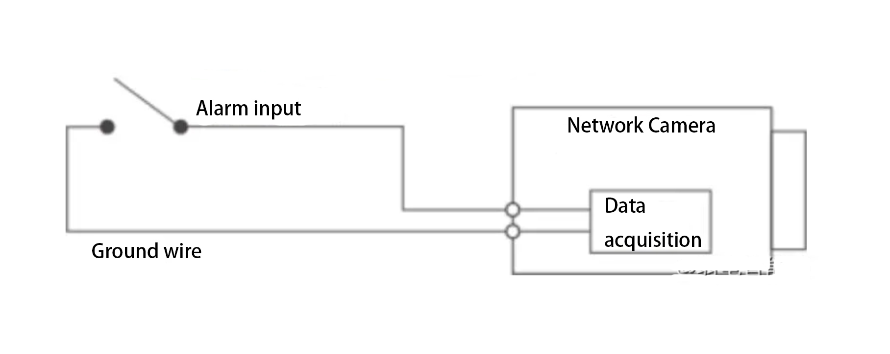
The input signal can either be floating or grounded, and the device can detect different states at the alarm input port.
- When the input signal is connected to +3V to +5V or is floating, the device detects a logic “1”.
- When the input signal is grounded, the device detects a logic “0”.
Step 2: Connect the alarm output device, as shown in the diagram below.
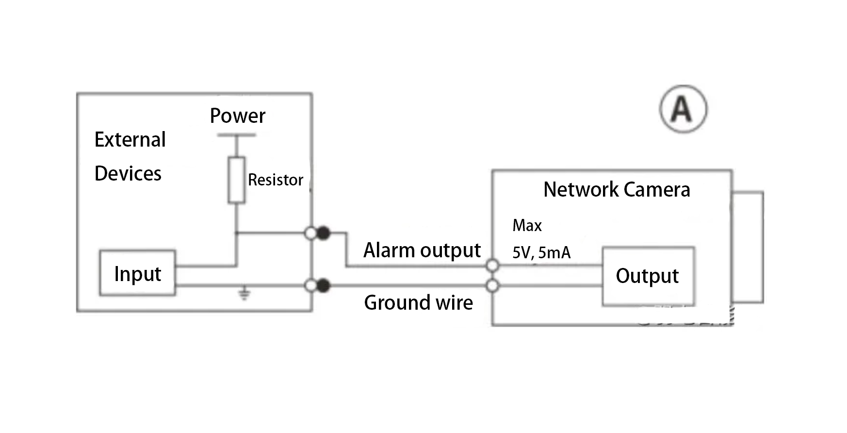
The alarm output is an open-drain (OD) output.
Method A: Level Application.
The alarm output provides high and low levels. The alarm output port is an OD gate, and an external pull-up resistor (typically 10kΩ) is required for proper operation.
The maximum external pull-up voltage is 5V, with a maximum port current of 5A. When the external pull-up resistor is added, the output signal is set to high (external pull-up voltage) by default. When an alarm is triggered, the output signal switches to low (the output voltage is less than 0.8V when the working current is below 5mA).
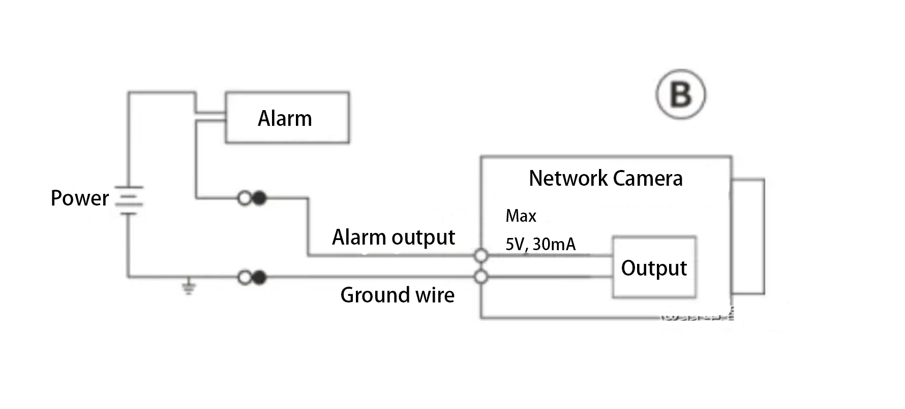
Method B: Switch Application.
The alarm output can drive an external circuit, with a maximum current of 30mA and a maximum voltage of 5V. If the current exceeds this limit, a relay is recommended.
Step 3: Log in to the Web interface and configure the alarm input and output settings accordingly.
The alarm input on the Web corresponds to the alarm input interface on the I/O port cable.
- If the input signal is a logic “0” when the alarm occurs, set it as a normally open input (default state).
- If the input signal is a logic “1” when the alarm occurs, set it as a normally closed input.
On the Web interface, configure the alarm output, which corresponds to the alarm output interface on the I/O port cable.